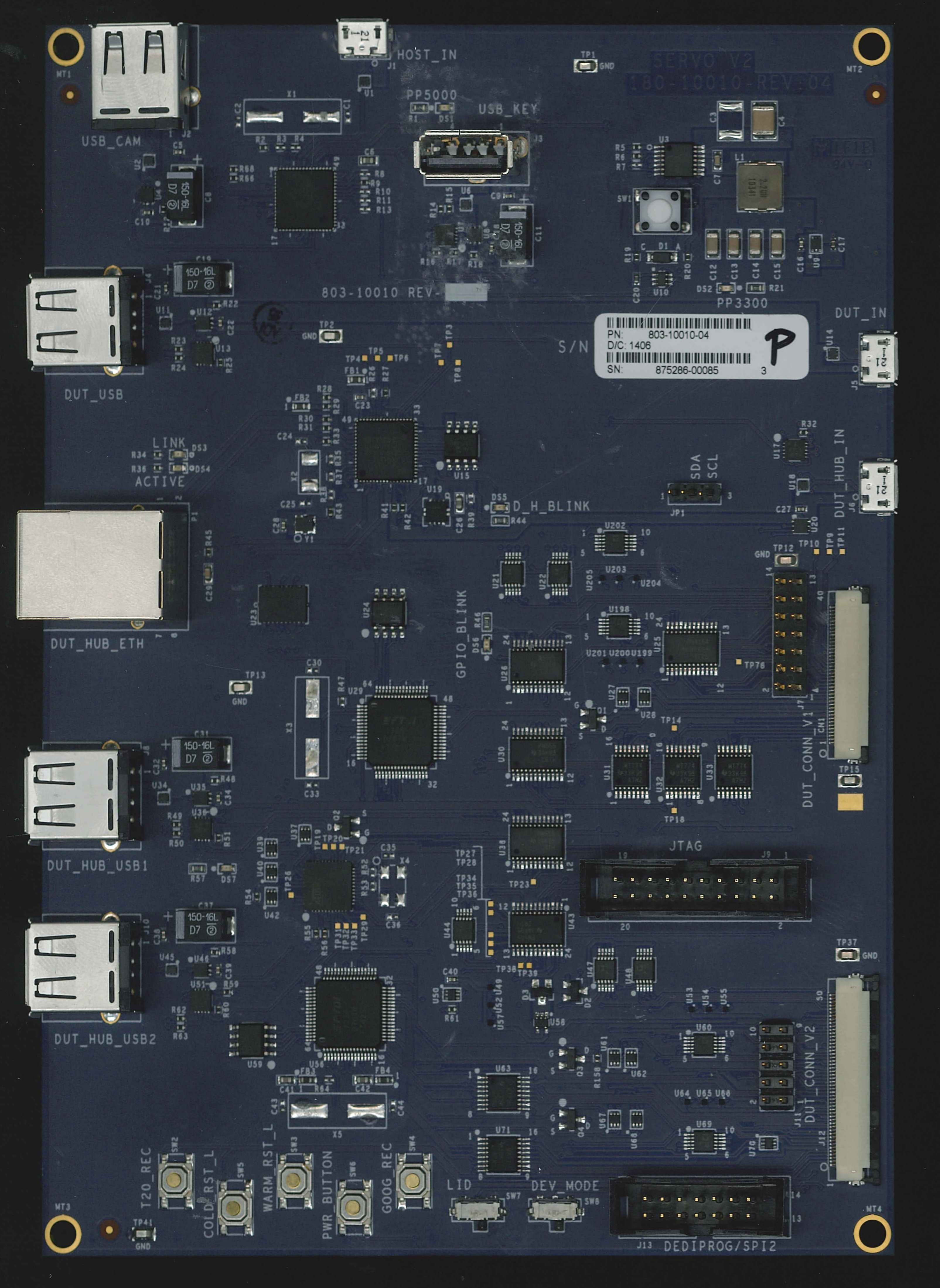
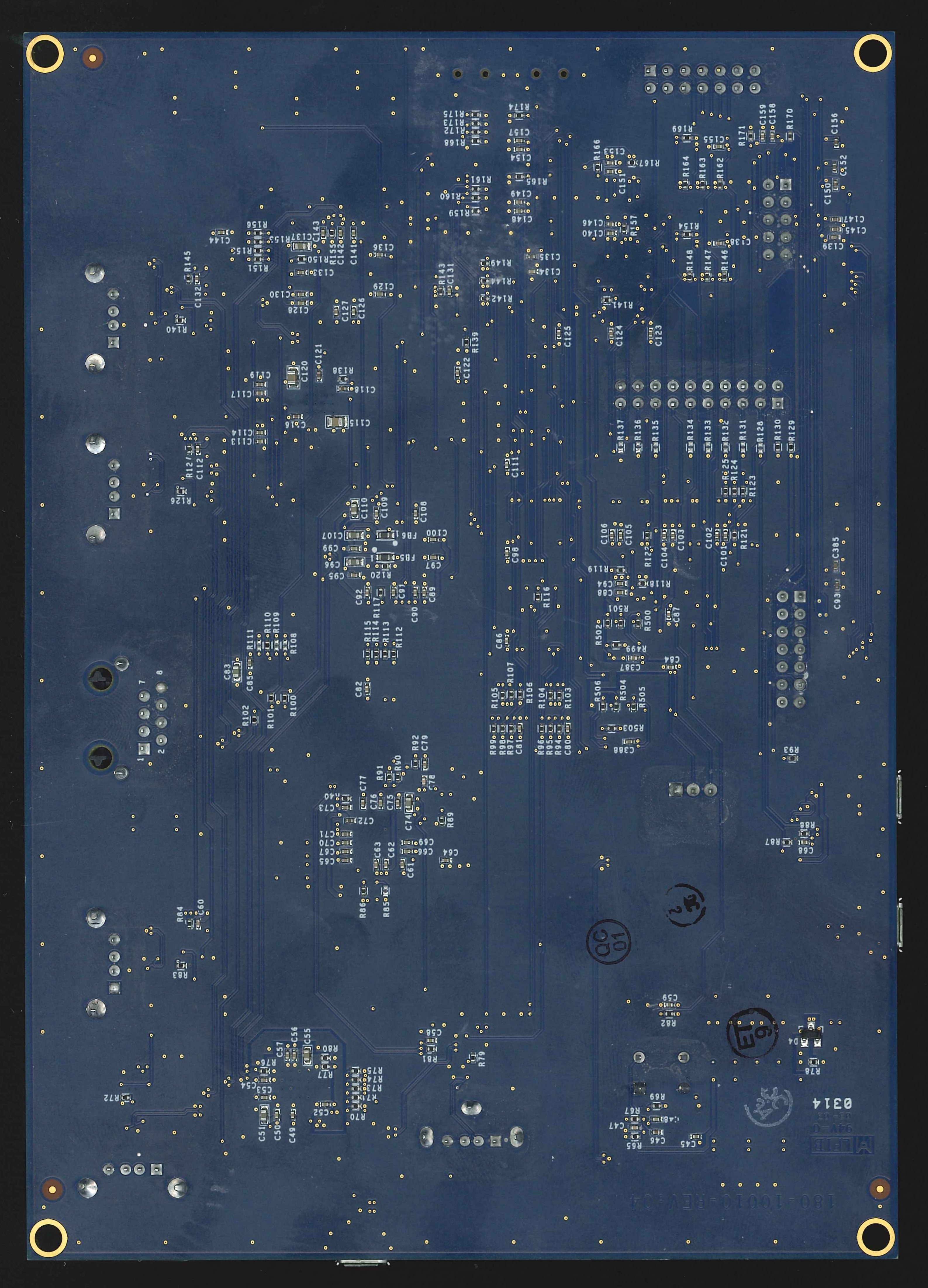
Servo v2 is a debug device in the Servo family. It is no longer manufactured, but still frequently used for early bringup or in cases where JTAG/SWD is needed.
Though Servo boards are not publicly distributed or sold (by Google), detailed information is available:
Stop by your local Chromestop.
In a typical debug setup, you connect Servo v2 to the debug header on a Chrome OS device, and to a host machine through the HOST_IN USB port.
Modern Chrome OS mainboards connect to Servo v2 with a 50-pin “Yoshi” flex cable. The schematic and layout for this cable is also available. The standard DUT-side debug header is an AXK750347G from Panasonic, though shorter variants are sometimes used.
The basic steps to connect Servo v2 are:
You should be able to use the power button on Servo v2 to power the Chrome OS device on and off.
Follow the general using Servo instructions.
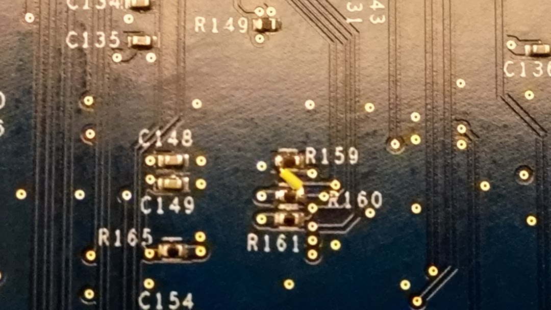
The Yoshi Flex cable is used to connect Servo v2 to a servo header. The standard cable does not work with Serial Wire Debug (SWD), but a simple rework can be performed to support SWD.
| Standard Yoshi Flex | Yoshi Flex Reworked to Support SWD |
|---|---|
Rework steps:
Some Dauntless(D2) daughtercards (D2DB) come with chips with non-production firmware. Another situation when the D2 chip needs hardware based recovery is when the chip was programmed with an RW firmware which malfunctions and does not allow any more firmware updates.
The only way to recover D2 in this state is to use the spiflash utility, which programs RO and RW firmware simultaneously. This will destroy the D2 identity, but at least will allow using it for board bringup.
Servo v2 allows to use spiflash to re-program D2.
A pull up on dev_mode line is required to allow enabling D2 SPI flash programming mode. On servo-v2 the pull up needs to be connected between pins j7:6 and j11:8, any value from 1k to 1M should be fine.
To enable D2 firwmare flashing run
 $ dut-control -- spi1_buf_en:on spi1_buf_on_flex_en:on spi1_vref:pp3300
 $ dut-control -- dev_mode:on pch_disable:on pch_disable:off
At this point the boot prompt should show up on D2 console:
Ravn4|00100000 7f4bdb+
boot :
and spiflash utility can be used to send the new firmare to the chip.


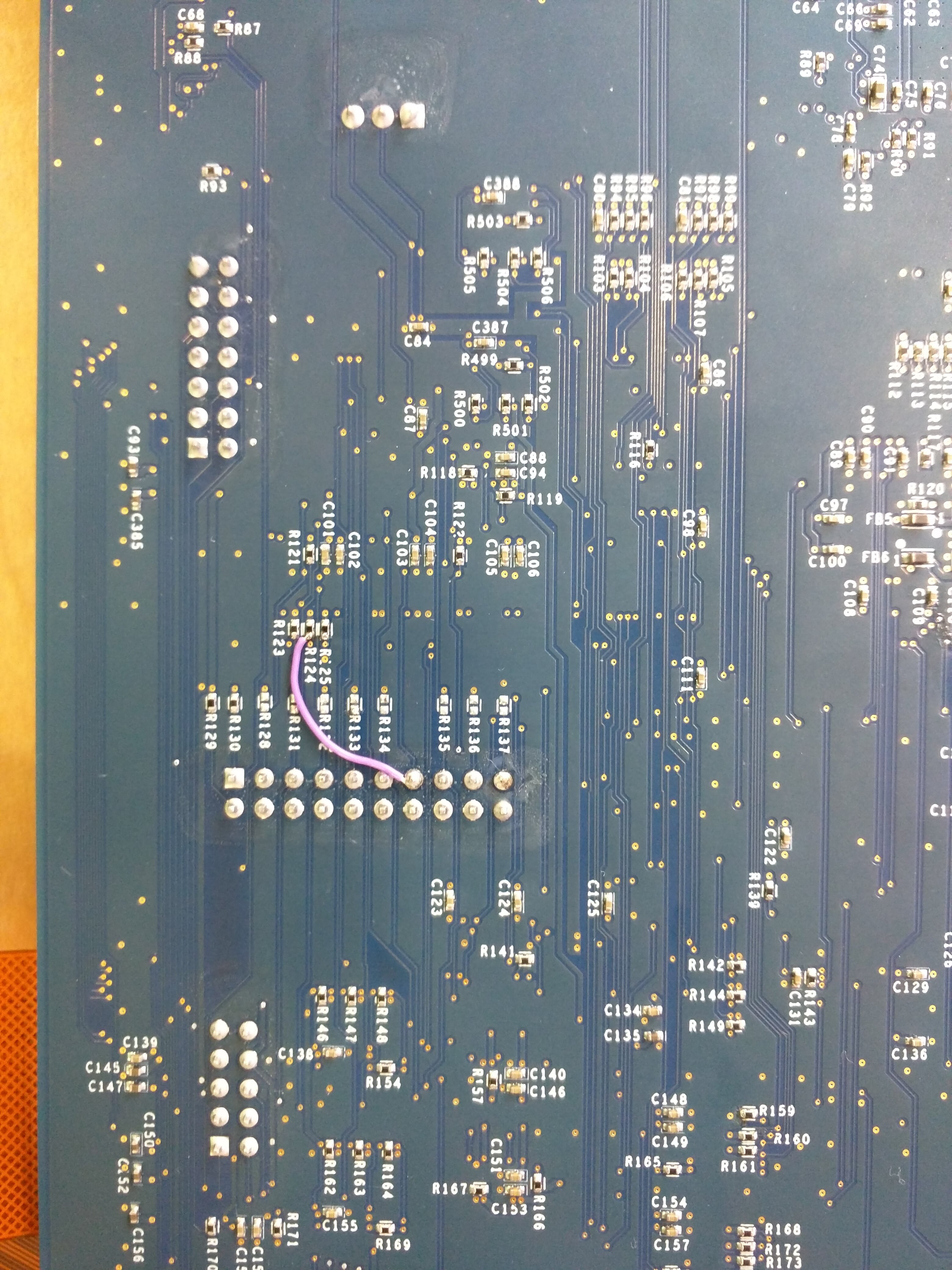
On Servo v2, by default the GSC/USBPD UART is not enabled and requires a rework. If this is not done, any GSC controls will fail with a timeout since the console is not hooked up.
Something like the following might show up on initialization:
cr50 - WARNING - Consider checking whether the servo device has read/write access to the Cr50 UART console.
Servod - ERROR - Problem initializing cr50_version -> print
This issue can be solved by a rework.
Servo v2 reworks are needed to flash the PD MCU on certain boards and access the PD MCU console. These reworks are not mutually compatible, so only apply the one relevant to your board.

