breadcrumbs: Testing Home > page_name: chamelium title: Chamelium
Chamelium automates external display testing across VGA, HDMI, and DisplayPort (DP), helping to identify graphics bugs and regressions in a reliable and scalable way. It can emulate user behavior across a wide range of scenarios, such as plugging in (or unplugging) an external monitor before or after suspending, waking, or rebooting a device. It also allows us to simulate all types of displays on the market, at various resolutions and refresh rates, including non-standard or flaky behavior.
Chamelium is the public name of the internal Google project Chameleon (similar to Chromium and Chrome). You may see references to the original codename throughout the documentation linked below.
Chamelium consists of 3 primary components:
a hardware board which acts as an external display emulator, simulating
output over VGA, HDMI, and DP. You can either ask a hardware manufacturer to
build these for you, or contact
[chamelium-external+requests@google.com](mailto:chamelium-external+requests@google.com)
to request a few units.

an off-the-shelf FPGA board (SoCKit) to capture the output frames, with a
micro-SD card that provides the Linux image and FPGA configuration. This can
be purchased from distributors like
[Arrow](https://parts.arrow.com/item/detail/arrow-development-tools/sockit#eFGz)
or [Terasic](http://www.terasic.com.tw/cgi-bin/page/archive.pl).

source code for the underlying test infrastructure and logic
Please direct any questions about Chamelium to chamelium-external@google.com.
Setting up Chamelium

(Block diagram)
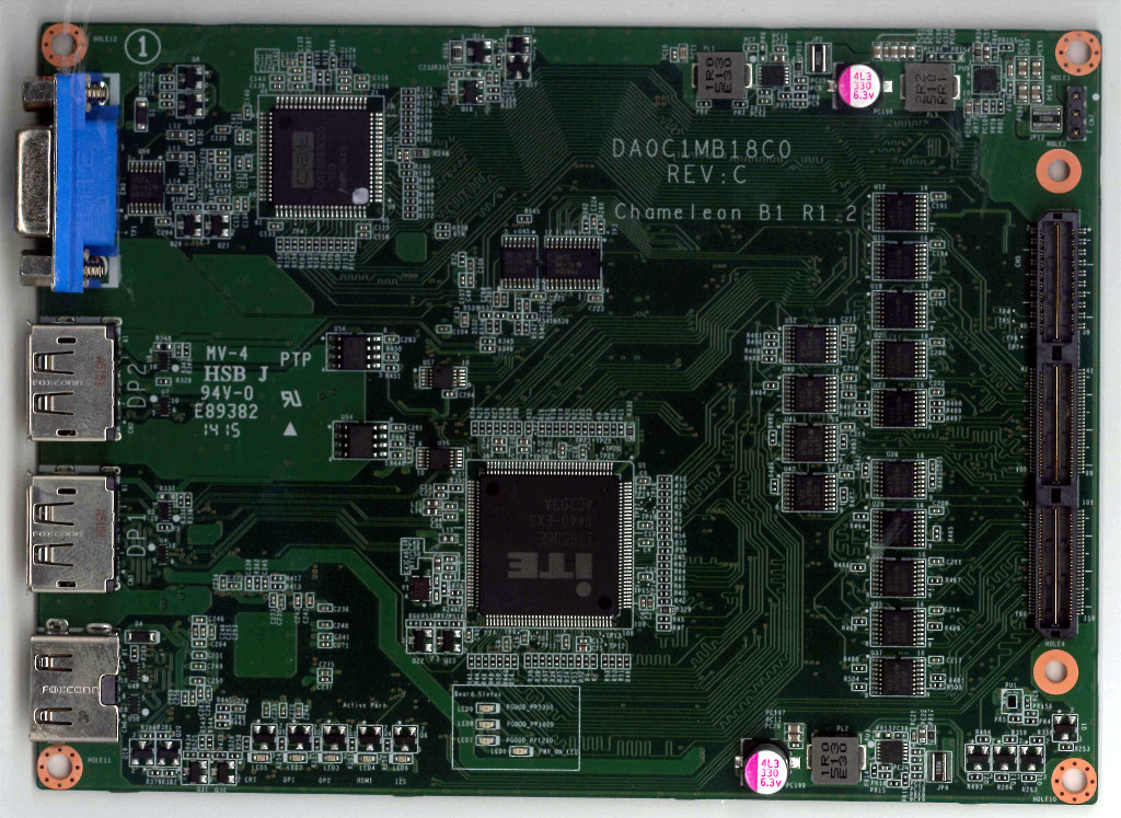
(Front side of the external display emulator board. On the left side there is one HDMI, two DP, and one VGA connector. On the right side there is the HSMC connector.)
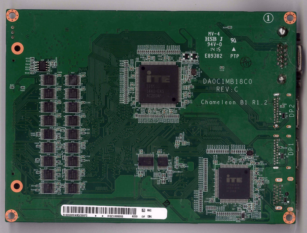
(Back side of the external display emulator board)
You will need the following equipment to set up all the individual components in Chamelium:
1 external display emulator board (described above)

1 FPGA board (described above). Included in the box should be:

    1 ethernet cable

    1 power adapter

    1 mini-USB to USB-A cable

1 micro-SD card with at least 1GB of storage

1 micro-SD card reader

[1 HSMC flex cable](http://www.terasic.com.tw/cgi-bin/page/archive.pl)

Depending on what you’d like to test, one of each of the following cables:
HDMI, VGA, and DP

1 Linux host (workstation or laptop)

1 USB drive with at least 4GB of storage
The following equipment is optional:
4 [M3 screws](https://en.wikipedia.org/wiki/Computer_case_screws#M3_screw)
(6mm in length)

2 washers

4 M3 nuts (15mm in length)

4 M3 nuts (6mm in length)

1 additional VGA cable and 1 external monitor for debugging, if you’d like
to see the display output as well
Configure the FPGA board
Set the jumpers on the top side of the board
J15 = down
J16 = down
J17 = up
J18 = up
J19 = down
JP2 - 2.5V


Set the jumpers on the bottom side of the board
MSEL = up-up-down-up-up-up = uncompressed RBF (001000)

Image the SD card
Download tio_v2_4G.img.zip and unzip it. dd tio_v2_4G.img onto the micro-SD card from your Linux host.
sudo dd if=tio_v2_4G.img of=/dev/sdx bs=4M oflag=sync
(Replace the above /dev/sdx to a proper path, like /dev/sdc, by checking the SD device)
Now insert the micro-SD card into the FPGA board.
Updates on v2 image:
Increased user space from 20M to 4G.

Updated glibc from 2.15 to 2.29.

Fixed broken pip.
Old v1 image: tio.image.gz
Configure the external display emulator board
First, attach the HSMC flex cable to connect the two boards.
Optionally, if you’d like a more compact setup, you can stack the FPGA on top of the external display emulator board and secure them into place per the diagram below:

Note that the longer nuts should be placed in between the two boards, with the shorter nuts on the bottom.
Attach all cables
Attach the power and HDMI, DP, and/or VGA cables (depending on what interface you’d like to test), per the diagram below. Connect the other end of the HDMI, DP, and/or VGA cable to the device under test (DUT) - the device you’d like to run the tests against. Then connect the mini-USB port in the diagram below to your Linux host. The additional VGA port next to the ethernet port is optional (it’s for debugging purposes only) and should be connected to an external monitor if you decide to use it.  Next, connect the ethernet port on the FPGA to the same network as your Linux host and as your DUT.
Running the tests
Verify your network setup
Power on the FPGA board by pressing the red button. This will boot from the
SD card.

Connect to the board via UART
sudo minicom -D /dev/ttyUSB0 -o -w -s
Select Serial port setup

Set the terminal to be 115200 8N1, and the Hardware Flow Control to No

Select Save setup as dfl to save these changes as the default

Restart the FPGA board

Once the FPGA is done booting, login as root

Make sure you can ping the FPGA board from your Linux host, and the Linux
host from your FPGA. You may need to setup a DHCP server on your Linux host.

Switch your DUT into developer mode

Finally, make sure you can ping the DUT from your Linux host.
The IP address will change at each reboot, as the MAC address of the board is not fixed. You can fix it by running the following commands in uboot (change XX to hex numbers of your choice):
> setenv ethaddr 0A:XX:XX:XX:XX:XX
> saveenv
> boot
Setup your Linux host, DUT and the FPGA
[Checkout the source
tree](http://www.chromium.org/chromium-os/developer-guide) for Chromium OS

[Create and enter a
chroot](http://www.chromium.org/chromium-os/developer-guide#TOC-Building-Chromium-OS)
via the command cros_sdk

Build the packages and images to run the tests
export BOARD=[name of your DUT’s board, viewable at chrome://version]
./setup_board --board $BOARD
./build_packages --board=$BOARD
[Install Chromium OS onto your
DUT](/chromium-os/developer-guide#TOC-Installing-Chromium-OS-on-your-Device)

    Connect your USB drive to your Linux host

    Build a test image
./build_image --board=$BOARD test
    Run the command displayed in the output in the terminal, under the
    section, “To copy the image to a USB key, use…”
cros flash usb:// ../build/images/[...]/chromiumos_test_image.bin
    Now, boot your DUT from the USB drive (with the test image) - you’ll
    need to [enter
    vt2](/chromium-os/developer-guide#TOC-Getting-to-a-command-prompt-on-Chro),
    login as root, and run enable_dev_usb_boot. Then, connect your USB drive
    to your DUT and restart - you’ll need to enter \[Ctrl\]-\[u\] at the
    developer mode boot screen.

    After the DUT has booted, switch to vt2, login as root (the password on
    the test image is test0000) and run chromeos-install .
chromeos-install
    Shutdown the DUT, disconnect the USB drive, and then turn on the DUT.

On your Linux host, setup the ARM toolchain and set the relevant environment
variables
cd ~/trunk/src/scripts
./setup_board --board arm-generic
export CHAMELIUM_IP=[IP address of the FPGA board]
export DUT_IP=[IP address of the DUT]
Make and deploy chameleond on the FPGA
cd ~/trunk/src/platform/chameleon
make
make remote-install CHAMELEON_HOST=$CHAMELIUM_IP
Setup root password and SSH key
- There is no password by default. For security concern, we should set the password.
- Set the password on FPGA
passwd
- In Chromium OS chroot, copy the public key to FPGA and check it works.
ssh root@$CHAMELEON_IP mkdir -p .ssh
cat ~/trunk/chromite/ssh_keys/testing_rsa.pub | ssh root@$CHAMELEON_IP 'cat
>> .ssh/authorized_keys'
ssh $CHAMELEON_IP
Run the tests
Set $TEST_NAME to any of the following. Please note that the starred test
items (\*) require [servo](/chromium-os/servo), and will fail without it.

    display_ServerChameleonConnection

    display_ClientChameleonConnection

    display_SwitchMode

    display_HotPlugAtBoot.extended

    display_HotPlugAtBoot.mirrored

    display_HotPlugAtSuspend.extended

    display_HotPlugAtSuspend.mirrored

    display_HotPlugAtSuspend.extended_unplugged

    display_HotPlugAtSuspend.mirrored_unplugged

    display_Resolution.extended

    display_ResolutionList.extended

    display_Resolution.mirrored

    display_Resolution.reboot

    display_Resolution.relid_extended\*

    display_Resolution.relid_mirrored\*

    display_Resolution.suspend_resume

    display_HotPlugNoisy.extended

    display_HotPlugNoisy.mirrored

    display_LidCloseOpen.extended\*

    display_LidCloseOpen.mirrored\*

    display_LidCloseOpen.extended_unplugged\*

    display_LidCloseOpen.mirrored_unplugged\*

    display_SuspendStress.extended

    display_SuspendStress.mirrored

    display_EdidStress
export TEST_NAME=[name of the test you’d like to run]
Alternatively, you can run an entire test suite by setting $TEST_NAME to
either of these values, below. Each suite consists of a combination of the
individual tests listed above.

    suite:chameleon_hdmi

    suite:chameleon_dp

Run a test [using
test_that](/chromium-os/testing/test-suites#TOC-How-to-run-suites-with-test_that-)!
cd ~/trunk/src/scripts
test_that --board=$BOARD --args “chameleon_host=$CHAMELIUM_IP” $DUT_IP
$TEST_NAME
Advanced usage
For additional instructions on how to modify tests or the FPGA image, please refer to the documentation below.
The hardware specs include:

    Schematics (see attachment: Chameleon-B1_R1.2_Release \[for external
    use\].pdf)

    Board file (see attachment: Chameleon_B1_R1.2_Release.brd)

    HDMI receiver (see attachments: IT6803TE Datasheet_for_Google v0.83.pdf
    and IT6803 Programming Guide.1.05.pdf)

    DP receiver (see attachments: IT6506_Datasheet_for_Google_v1.3.pdf and
    IT6506 Programming Guide.pdf)

    VGA receiver (see attachments: cat9883c_datasheet_for_Google_Rev1 3.pdf
    and CAT9883CRegisterRev01.pdf)

    [Chamelium Hardware Design
    Overview](https://docs.google.com/document/d/1Ae_qcraDwNA5dkWkVo3PhK2SQzZITTv-rlDUFE5tybI/edit)

    [Chamelium External Display
    Emulator](https://docs.google.com/presentation/d/1p8F8defw3fQzCtUyZyoQjROQ37jIZRDwkBT9XG2Cj3g/edit)

    [HSMC pin
    mapping](https://docs.google.com/spreadsheets/d/1ISQF5VookmiZWYXKs4fedR6LO5MDmiH0V1v1EMsuiPc/edit)

    [FPGA pin
    mapping](https://docs.google.com/spreadsheets/d/1AkgGdehgp27SnCDMjQ6qxNdfmGV2NTp9bAL8llEtLUo/edit)

    FPGA pin locations (see attachment: FPGA pins.png)

    [HSMC spec](http://www.altera.com/literature/ds/hsmc_spec.pdf)
- The FPGA specs:
- FPGA Development Guide
- FPGA Interface
- FPGA RTL Source Code (see attachment: video-chameleon-658cadce37849ec8330f7cbfa01135983984ec24.tar.gz)
- Test software:
- chameleond - daemon to drive the hardware and expose its control interfaces
- test harness - library in autotest harness to interact with chameleond
- tests cases - modular test cases that are meant to represent real-world, end-user behavior